

|
|
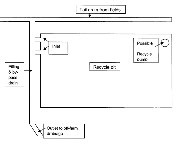
Recycle pitsRecycle pits — Planning and design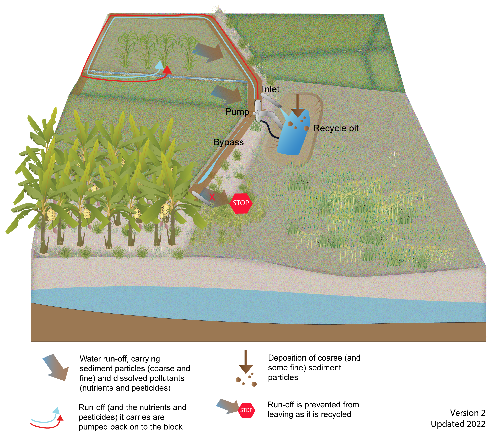 Select from the tabs below Site selectionRecycle pits should be located:
SizingThe recycle pit needs to be large enough to capture all the tailwater of an irrigation event and/or a rainfall event (depending on the purpose of the pit). As it can be impractical to operate the recycle pit empty, an allowance for 10% additional capacity will minimise the risk of the recycle pit overflowing. Capturing irrigation eventsTo calculate the minimum storage volume required for capturing irrigation tailwater requires an understanding of:
For example, a general rule of thumb used to calculate the size of a recycle pit in the Burdekin River Irrigation Area is to have a recycle pit of 5-10ML for each 100ha of irrigation lands. To make it cost-effective for the producer (i.e. sufficient water to offset the costs of storage, pumps and pipelines), a minimum area to supply the storage is around 200ha[6]. Capturing rainfall eventsRecycle pits can also be designed to capture run-off from a specific sized rainfall event. Small to medium sized rainfall events during the dry season and early wet season can have the highest concentrations of pollutants and pose the highest risk to freshwater, estuarine and inshore marine environments[2]. Recycle pits can be sized and designed to capture and re-use run-off from these events. The minimum size required to capture stormwater run-off will depend on the characteristics of the catchment, the amount of stormwater run-off and pollutant load reductions required. Compare the projected stormwater run-off in megalitres (ML) (as calculated below) with the projected irrigation tailwater run-off and choose the larger volume to ensure that the recycle pit can effectively capture irrigation and stormwater run-off. The volumetric run-off coefficient (Cv) for a single storm event can be used to estimate the catchment run-off volume for the design storm event. The Cvis defined as the ratio of the volume of stormwater run-off to the volume of rainfall that produced the run-off and is influenced by soil type and vegetation density[3]. Table 1 provides Cv for different soil types and if the soil texture is unknown a Cv of 0.5 should be used. The net run-off (ML) = Catchment area (ha) x rainfall event (mm) x volumetric run-off coefficient (Cv) ÷ 100 Table 1 Volumetric run-off coefficient values (Cv) for different soil types. Source: NRW 2000 in DEEDI (2011)
The length, width and depth of the recycle pit will need to be tailored to the site, so that it avoids disturbing or leaking to groundwater or natural areas and also minimises impact on the production areas and farm operations. Design
Macrophytes such as reeds and sedges can be used in recycle pits to enhance pollutant treatment and provide habitat. Guidelines for cotton and grain production areas, recommend separate cells to minimise evaporative loss and to enable different functions in each cell, i.e. one cell with macrophytes to help treat the water (e.g. removal of fine sediments and some pesticides), another cell with open water to enable sunlight to break down pesticides and the final cell (i.e. cleanest water) with habitat for fauna[5]. Unless designed specifically for habitat purposes, fish and wildlife should not be encouraged in recycle pits where water quality and dissolved oxygen levels are often poor as to cause fish kills. DisclaimerIn addition to the standard disclaimer located at the bottom of the page, please note the content presented is based on published knowledge of treatment systems. Many of the treatment systems described have not been trialled in different regions or land uses in Queensland. The information will be updated as new trials are conducted and monitored. If you have any additional information on treatment systems or suggestions for additional technologies please contact us using the feedback link at the bottom of this page. References
Last updated: 10 June 2022 This page should be cited as: Department of Environment, Science and Innovation, Queensland (2022) Recycle pits — Planning and design, WetlandInfo website, accessed 8 May 2025. Available at: https://wetlandinfo.des.qld.gov.au/wetlands/management/treatment-systems/for-agriculture/treatment-sys-nav-page/recycle-pits/planning-design.html |
||||||||||||||||||||||||||||||||||||||||||||||||||||||||||||
Site footer

 — Department of the Environment, Tourism, Science and Innovation