Treatment wetlands may be placed to treat run-off from a single paddock or multiple paddocks (or ponds in the case of aquaculture). Larger treatment wetlands treating run-off from multiple farms are also possible.
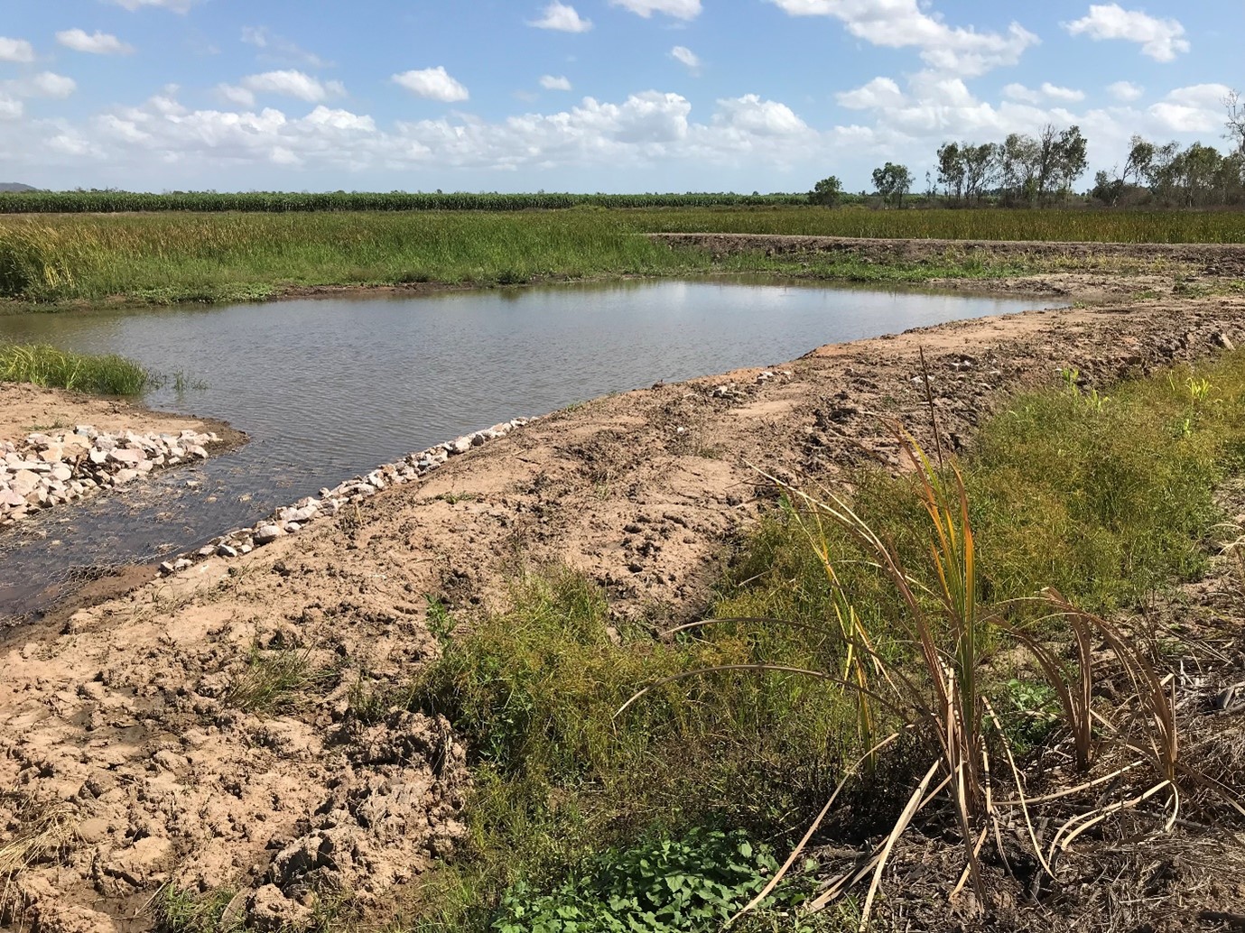
Treatment wetlands are ideally situated in low-lying areas that have low or no agricultural productivity and receive run-off from the production areas. Sites that were once wetlands and had been historically drained or cleared are often suited to hydrological modifications to retain water and create a type of treatment wetland, called landscape wetlands. Borrow pits or other artificial depressions can also be modified into treatment wetlands (Figure 5), to minimise costs. In some instances, spoil removed during wetland construction could be placed in other low lying production areas to enhance production for win-win outcomes (see: Cane case study). Sites need to be assessed on a case-by-case basis to avoid damaging, or changing water flow, to existing natural wetlands and disturbance of Acid Sulfate Soils.
Treatment wetlands should be located:
on a relatively flat part of the farm (to minimise earthworks i.e. cutting and levelling)
to receive water run-off from the production area (the target area for water quality improvement)
where there are suitable, non-permeable soils at the design depth and no shallow groundwater that the wetland will intercept, unless the wetland is specifically designed to treat shallow groundwater. Leaching to groundwater and contributing to rising groundwater is a concern in some catchments, in particular the lower Burdekin
upstream of sensitive natural wetlands and waterways
where there are no Acid Sulfate Soils likely to be exposed during construction
where tidal water cannot enter the wetland
ideally out of regularly inundated flood zones, where the water velocity or duration of inundation could damage the wetland.
There are different ways to calculate the size or volume of treatment wetlands and this depends on the degree of sophistication required. The size required will depend primarily on:
the target pollutant/s and level of treatment required
the management practices and pollutants generated in the upstream sub-catchment, including any other treatment systems
the water regime in the sub-catchment
the degree of connection between the sub-catchment and the wetland
the design and management of the treatment wetland
any other systems in the treatment train e.g. vegetated swales.
Modelling programs enable a range of site conditions to be entered to determine the size required to meet treatment objectives[9]. Different wetland modelling programs are described in a report by the Queensland Water Modelling Network (QWMN).
Professional advice is recommended to size the treatment wetland based on the conditions at the site. An estimate of the size required to effectively treat run-off is often required during the early site assessment stage and the methods below can help calculate an approximate size.
1. Percentage of catchment
To determine whether there is sufficient land available for a treatment wetland to treat the pollutants going into it, a simple ‘rule of thumb’ is to calculate the size of the wetland as a percentage of the upstream catchment. Some recommendations (e.g. Wetland Management Handbook[2]) are for wetlands to be between 2-10% of the size of the upstream catchment (provided best management practices are implemented).
2. Detention volume
The volume required for a treatment wetland can be estimated based on the required detention period for the target pollutant, by multiplying the detention period required to meet treatment objectives (in days) by the daily run-off, wastewater or irrigation tailwater volume that would enter the wetland (in L/day). For more information refer to the Wetland Management Handbook[2].
Detention volume (L) = detention period (days) x daily run-off (L/day)
3. Capturing rainfall events
Treatment wetlands can be sized to capture run-off from a specific rainfall event. Small to medium sized rainfall events during the late dry season and early wet season can have the highest concentrations of pollutants and pose the highest risk to freshwater, estuarine and inshore marine environments[1]. Treatment wetlands can be sized and designed to capture and treat run-off from these events. The volumetric run-off coefficient (Cv) for a single rainfall event can be used to estimate the catchment run-off volume for the event. The Cv is defined as the ratio of the volume of water run-off to the volume of rainfall that produced the run-off and is influenced by soil type and vegetation density[2] Table 1 provides Cv for different soil types and if the soil texture is unknown a Cv of 0.5 should be used. For more information refer to the Wetland Management Handbook[2].
The net run-off (L) = Catchment area (m2) x rainfall event (mm) x volumetric run-off coefficient (Cv)
Table 1 Volumetric run-off coefficient values (Cv) for different soil types. Source: NRW 2000 in DEEDI (2011)
Rainfall (mm)
Soil Hydrologic Group
Group A Sand
Deep (>1m), well drained sandy loams, sands or gravels
Group B Sandy Loam
Moderately deep (>0.5m), well-drained medium loamy texture sandy loams, loams or clay loam soils
Group C Loamy clay
Moderately fine clay loams, or loamy clays, or more porous soils that are impeded by shallow depth or low porosity subsoil
Group D Clay
Fine texture clays, soils with poor structure, surface-sealing, or expansive clays. Also soils with a permanent high watertable
10
0.02
0.10
0.09
0.20
20
0.02
0.14
0.27
0.43
30
0.08
0.24
0.42
0.56
40
0.16
0.34
0.52
0.63
50
0.22
0.42
0.58
0.69
60
0.28
0.48
0.63
0.74
70
0.33
0.53
0.67
0.77
80
0.36
0.57
0.70
0.79
90
0.41
0.60
0.73
0.81
100
0.45
0.63
0.75
0.83
Design
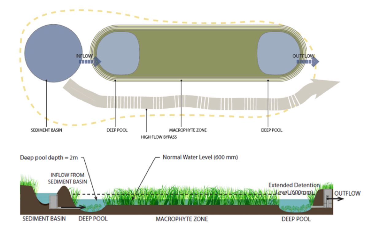
Treatment wetlands are recommended to have the following design features (shown in Figure 6) to maximise treatment performance. However, the actual design should be adapted to suit the objectives, site, and budget. Landscape wetlands, involving hydrological modification of a site to create the environment for pollutant removal, may not have all these design features. This could reduce treatment performance per hectare but might end up being more cost-effective for pollutant removal.
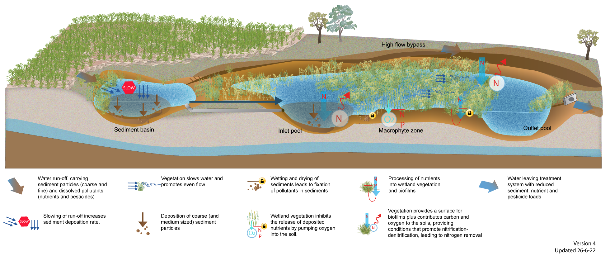
Sediment basin
A sediment basin is located where the water first enters the wetland system and has two key functions:
trapping coarse to medium sediment (>125µm) to avoid these sediments smothering the macrophyte zone
control flows entering the wetland (see sediment basins page for design requirements).
The normal water level in the sediment basin should be set at or above the normal water level in the macrophyte zone[8] and be lower than any adjoining production areas.
The sediment basin is often separate to the wetland, but it can also be built at the start of the wetland system (Figure 5).
Inlet zone
The inlet is the connection between the sediment basin and the macrophyte zone and is designed to allow the design flows to enter the macrophyte zone, with excess flows diverted to a bypass. Design flows are typically up to one year average recurrence interval (ARI) event flow[8]. ARI is an estimate of the average period in years between a flood occurrence of a given magnitude[5], therefore a one year ARI event means an event that is likely to occur on an annual basis. The actual design flow will vary depending on the site and design. More information can be found on the Bureau of Meteorology website.
The inlet structure can be a pipe or weir.
It should be of a suitable gradient (e.g. at least 0.3%) and be designed to prevent blockages[8].
Deep pools
Deep, open water areas are generally located near the inlet and outlet of the macrophyte zone and in any bends in the wetland.
They are designed to retain water for the entire dry season to provide habitat for mosquito predators and provide some open water within the wetland system to prevent stagnation and enhance denitrification[4].
These areas should be between 1.2 to 2m deep, depending on the climate and site constraints[8][2].
Macrophyte zone
A densely vegetated macrophyte zone covering at least 50% of the total wetland area is essential for effective water treatment, particularly nitrogen removal[3].
The densely vegetated macrophyte zone will be seasonally inundated and designed to dry out periodically, although dry periods should not exceed 60-70 days at a time[7].
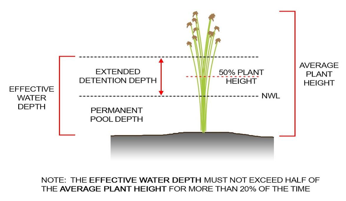
The design depth/normal water level of the macrophyte zone will depend on the climatic region and annual rainfall, but will generally be between 0.3-0.7m deep[8][7].
The normal water level should generally be higher than the water level in the receiving drainage infrastructure or waterway to allow water to passively flow out of the wetland to maintain flows through the wetland and avoid stagnation.
The macrophyte zone is designed to have an extended detention depth of around 0.3m (maximum 0.5m) above the normal water level[8] to limit the risk of drowning the wetland plants. The normal and extended detention depths need to be considered when selecting plants for different zones of the wetland to ensure they are suited to the water depth. In general, the water depth should not exceed half the average plant height for more than 20% of the time (Figure 7)[8]. An assessment of water levels requires a water balance and/or assessment of the hydraulic capacity of the wetland outlet to achieve an appropriate hydraulic retention time. Input from a wetland designer or hydraulic engineer should be sought.
The bathymetry of the macrophyte zone should provide uniform water flows (no short circuiting) and avoid isolated pools.
The length to width ratio of the macrophyte zone should be greater than 3:1 to maximise hydraulic efficiency[8][6][3].
Curved edges are recommended and there should be no islands in the macrophyte zone as these can impact hydraulic efficiency and reduce treatment performance.
The macrophyte zone can be broken up into cells or a series of small wetlands. This could be a way to stage construction.
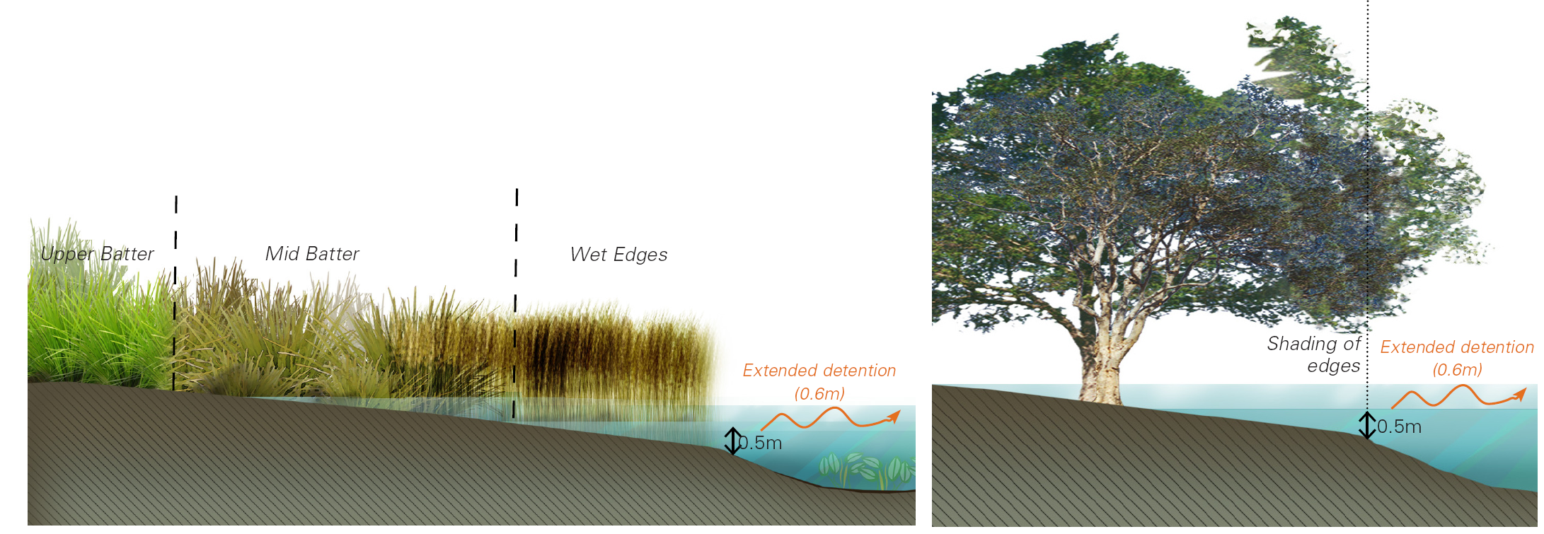
The batters should be planted densely with macrophytes and riparian species suited to the different depths. See Plant Guides for more information. At least 90% cover is recommended (e.g. six plants per square metre) as densely vegetated emergent macrophytes along littoral zones can make it difficult for weeds to establish by occupying the habitat (Figure 8).
Native trees, shrubs and grasses planted around the edge (with a minimum 5 m width) of the wetland can help shade out invasive species, reduce water temperature/evaporation and enhance habitat for biodiversity around the wetland.
Outlet
The outlet of the macrophyte zone is an important hydraulic structure to control water level and flow to achieve the required detention time. It can include a riser outlet designed such that the water level can rise to the extended detention depth then gradually draw down to the normal water level. A leaky weir can also be used as an outlet.
There should be provision for the wetland to be drained for maintenance purposes and to control water levels in the macrophyte zone during establishment.
High flow bypass
A high flow bypass is often a channel or drain from the sediment basin or inlet to downstream of the outlet, designed to convey excess flows when the wetland is full. High velocities through the wetland can damage the macrophyte zone and cause resuspension of pollutants. It may not be possible to position the wetland away from the flow path of extreme storms. In these cases, high flow velocities through the wetland should not exceed 2m/sec[8][7].
Disclaimer
In addition to the standard disclaimer located at the bottom of the page, please note the content presented is based on published knowledge of treatment systems. Many of the treatment systems described have not been trialled in different regions or land uses in Queensland. The information will be updated as new trials are conducted and monitored. If you have any additional information on treatment systems or suggestions for additional technologies please contact us using the feedback link at the bottom of this page.
References
^ Davis, AM, Pearson, RG, Brodie, JE & Butler, B (2016), 'Review and conceptual models of agricultural impacts and water quality in waterways of the Great Barrier Reef catchment area', Marine and Freshwater Research, vol. 68, pp. 1-19.
^ab Kavehei, E, Hasan, S, Wegscheidl, C, Griffiths, M, Smart, JCR, Bueno, C, Owen, L, Akrami, K, Shepherd, M, Lowe, S & Adame, MF (22 November 2021), 'Cost-Effectiveness of Treatment Wetlands for Nitrogen Removal in Tropical and Subtropical Australia', Water. [online], vol. 13, no. 22, p. 3309. Available at: https://www.mdpi.com/2073-4441/13/22/3309 [Accessed 21 December 2021].
^ Kavehei, E, Roberts, ME, Cadier, C, Griffiths, M, Argent, S, Hamilton, DP, Lu, J, Bayley, M & Adame, MF (November 2021), 'Nitrogen processing by treatment wetlands in a tropical catchment dominated by agricultural landuse', Marine Pollution Bulletin. [online], vol. 172, p. 112800. Available at: https://linkinghub.elsevier.com/retrieve/pii/S0025326X21008341 [Accessed 27 April 2022].
^ Melbourne Water (2017), Wetland Design Manual, Melbourne Water, Melbourne.
^ Persson, J, Somes, NLG & Wong, THF (1999), 'Hydraulics efficiency of constructed wetlands and ponds', Water Science and Technology, vol. 40, no. 3, pp. 291-300.
^abcdefghi Water by Design (2017), Wetland Technical Design Guideline. [online], Water by Design, Brisbane. Available at: https://waterbydesign.com.au/.
^ Wong, T, Fletcher, T, Duncan, H, Coleman, J & Jenkins, G (2002), 'A model for urban stormwater improvement conceptualization', Global Solutions for Urban Drainage, pp. 8-13.
Last updated: 30 June 2022
This page should be cited as:
Department of Environment, Science and Innovation, Queensland (2022) Treatment wetlands — Planning and design, WetlandInfo website, accessed 8 May 2025. Available at: https://wetlandinfo.des.qld.gov.au/wetlands/management/treatment-systems/for-agriculture/treatment-sys-nav-page/constructed-wetlands/planning-design.html


 — Department of the Environment, Tourism, Science and Innovation