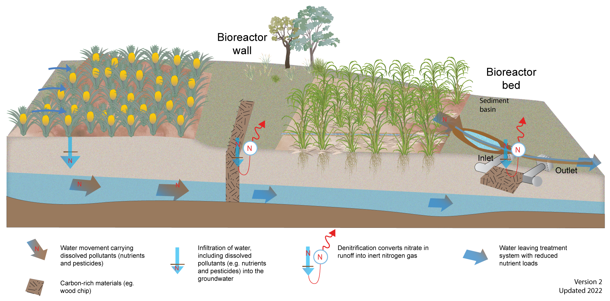
The first step is to understand the site within the broader landscape and the landholder’s objectives, to identify if bioreactors are a potential option.
The main characteristics to assess the suitability for either a bioreactor bed or wall are outlined in the table below.
Site characteristic
Bioreactor bed
Bioreactor wall
Water flow
Regular surface or sub-surface flow.
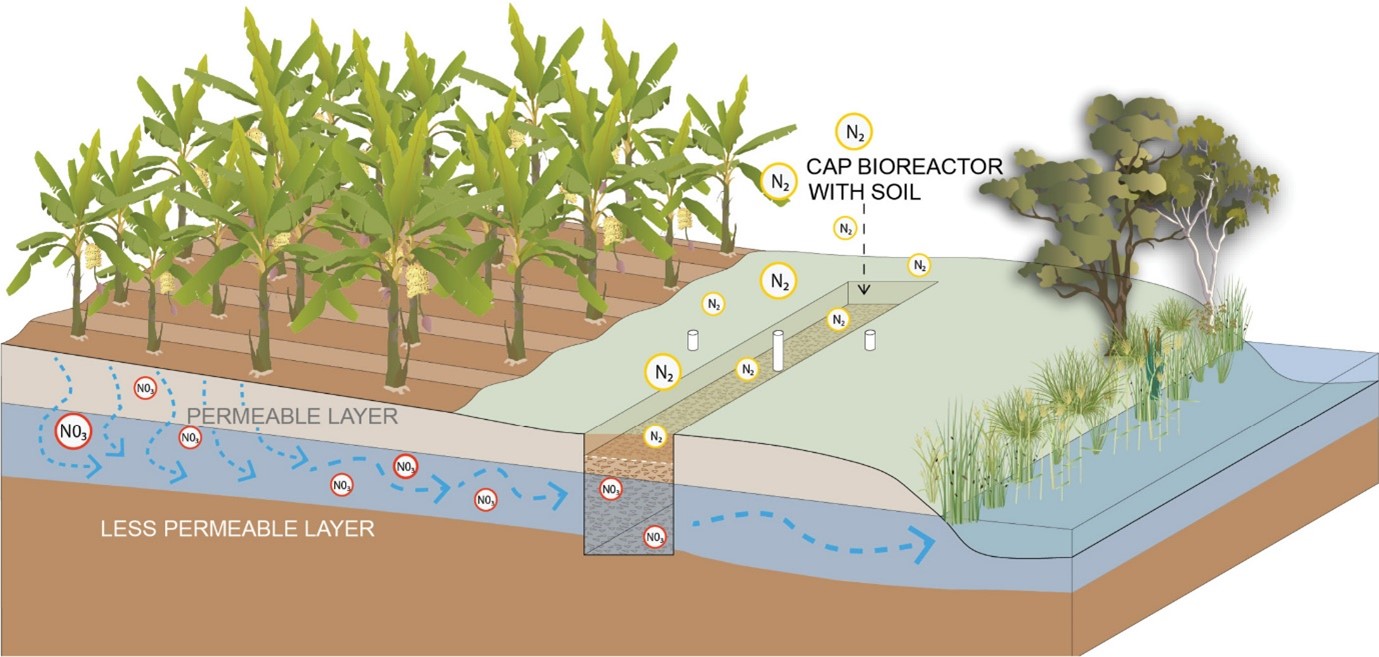
Shallow groundwater (within one metre of the surface) following rain or irrigation events, so that woodchip intercepts groundwater.
Nitrate concentration of water to be treated
At least 3mg N/L for most of the time.
At least 5mg N/L for most of the time.
Soil type
Avoid sites receiving flow from areas with erosive soils or high sediment loads as the sediment could block the bioreactor.
Sandy/sandy loam topsoil less than 3m depth, ideally underlain by less permeable clay or rock.
Topography
A site where there can be a gentle gradient from the inlet to the outlet to ensure water flows through the bioreactor.
Site where shallow groundwater flows. Note that groundwater often flows differently to surface water.
Position relative to production area
Point at which water leaves the production area, usually within or parallel to drainage.
Downslope end of production area.
Other
Locate at least 10m upstream of a sensitive waterway or wetland to enable outflow to re- oxygenate. Avoid areas used by vehicles. Avoid disturbing native vegetation or wetlands.
Avoid areas that are regularly inundated.
Headlands receiving light traffic may be suitable. Avoid disturbing native vegetation or wetlands.
A site survey should determine:
Site suitability relative to soil type, production areas and farm activities and the landholder’s agreement.
Nitrate concentration of water to be treated and variability throughout the year.
Hydrology (water flow during different rainfall and irrigation events, presence of shallow groundwater and subsurface drainage).
For cost-effective nitrate removal, bioreactors should be located where nitrate levels in the water to be treated is at least 5mg N/L for bioreactor walls and 3mg N/L for bioreactor beds, for most of the time.
Sizing
Bioreactor bed
Beds are sized based on the water flow to be treated and the hydraulic residence time required to reduce nitrate by a given concentration. A hydraulic residence time of at least three hours is recommended to allow the dissolved oxygen levels to reach suitable concentrations for denitrification[3][1]. The following information is needed to estimate the volume of woodchip required in a bioreactor bed:
Target water flow rate (e.g. m3/hr), based on the flow rate in the drain or pipe and the percentage of flow to be treated.
The nitrate concentration of the water to be treated and the amount of nitrate to be removed.
The amount of nitrate reduced per hour within the bioreactor (a generic nitrate concentration decline rate of 0.8 mg N/L/hr has been estimated from the bioreactor bed trials in North Queensland)[3].
A formula for estimating the size of a bioreactor bed is provided in Using denitrifying bioreactors to improve water quality on Queensland Farms. Note that this formula is based on generic assumptions. A professional experienced in designing treatment systems must be used to design and calculate the sizing of a bioreactor based on the site characteristics, particularly soils and hydrology.
Bioreactor beds should have a length to width ratio of approximately 10:1[2]. Bioreactor beds deeper than 1m may require engineered bank reinforcement and can increase the construction cost.
Bioreactor wall
Generally, the width of a bioreactor wall is determined by the width of the excavator bucket. This will in turn determine the hydraulic residence time. A formula for estimating the width of a bioreactor wall, based on the groundwater velocity and hydraulic residence time required to remove the desired amount of nitrate, is provided in Using denitrifying bioreactors to improve water quality on Queensland Farms. The formula can be used to check what excavator bucket width is most appropriate. In most cases, standard excavator bucket widths will be sufficient to remove most, if not all, the nitrate in the water passing through a bioreactor wall[3].
Walls can be any length and are usually constrained by available land, funding and the extent of suitable site conditions. The depth of the wall is determined by the site conditions such as depth of groundwater and low permeability layer, if present.
Design
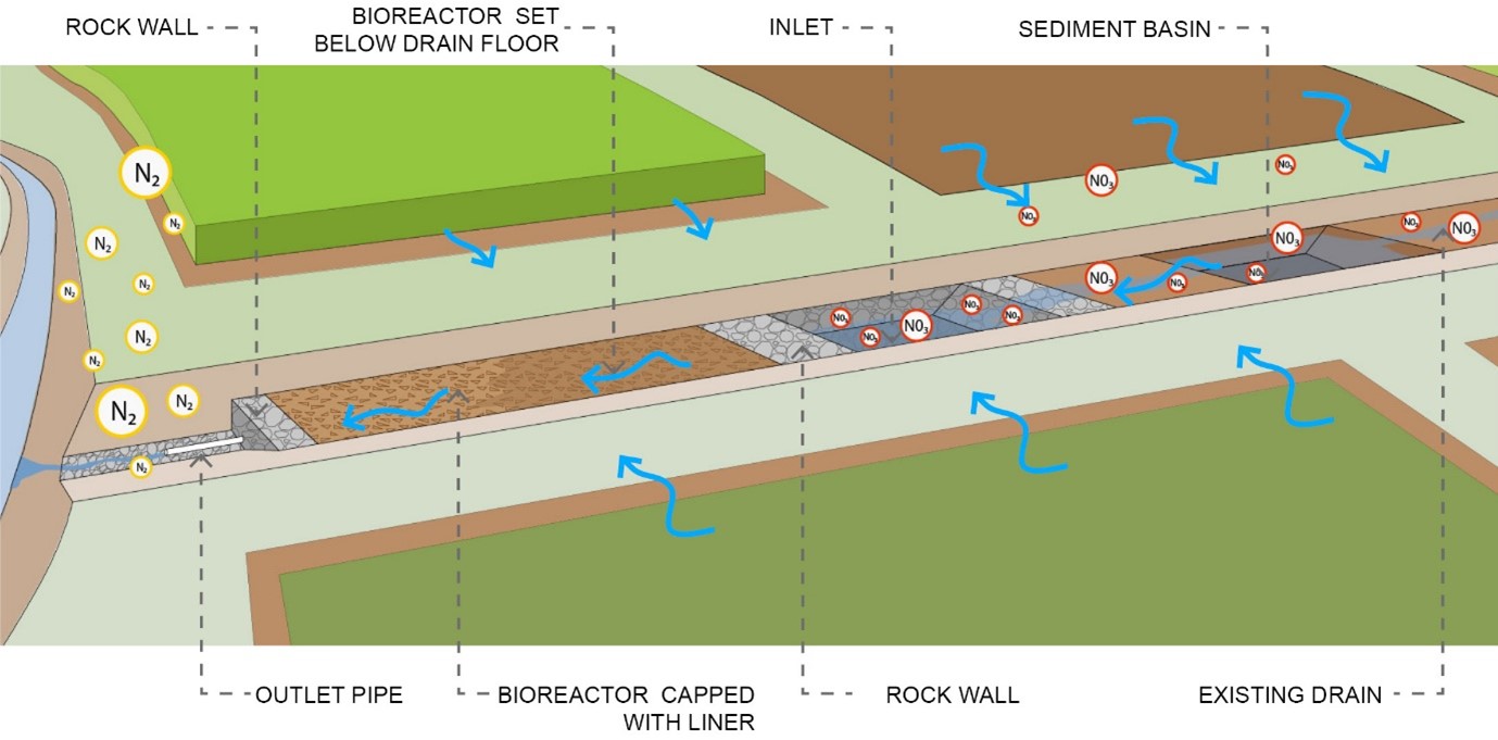
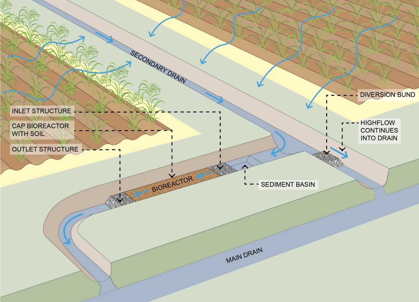
In-line and off-line bioreactor beds:
Sediment trap upstream to avoid sediment smothering the inlet or the woodchip.
Inlet structure designed to maximise hydraulic efficiency and hold the woodchip in place. This can be rock-filled gabion baskets, rock or pipes. If a single inlet pipe is used a spreader is necessary to disperse the water evenly through the woodchip. A gravel pit can be installed as part of the inlet structure to further minimise the risk of sediment entering the woodchip.
Outlet structures designed to avoid blockages by having multiple outlet pipes (if pipes are used) and to ensure sufficient residence time by sizing the outlet structure according to the flow and hydraulic residence time (valves can be used on outlet pipes to regulate flow).
The outlet can be either at the top or bottom of the woodchip depending on the slope of the site and how flow will be achieved through the bioreactor and whether the bioreactor needs to stay saturated or dry out. Keeping the bioreactor saturated will maintain low oxygen conditions within the bioreactor and could reduce degradation of the woodchip. However, there can be a risk of pollutant swapping under nitrate-limited, saturated conditions[4]. Making the outlet level adjustable can facilitate draining of the bed and ensure the outlet collects water from the full depth of the bioreactor, to minimise dead spots within the bed[3].
The woodchip should be enclosed in plastic to minimise soil entering the woodchip and enable the woodchip to be exposed later in the project if desired[3].
Topsoil of at least 0.1m depth placed on top of woodchip to prevent degradation of liner and to enable grass to grow on surface.
Excess flow bypass and scour protection for higher water flows.
If the bioreactor is immediately upstream of a sensitive waterway, a structure to reoxygenate the discharge (e.g. rock riffles) should be installed downstream of the outlet.
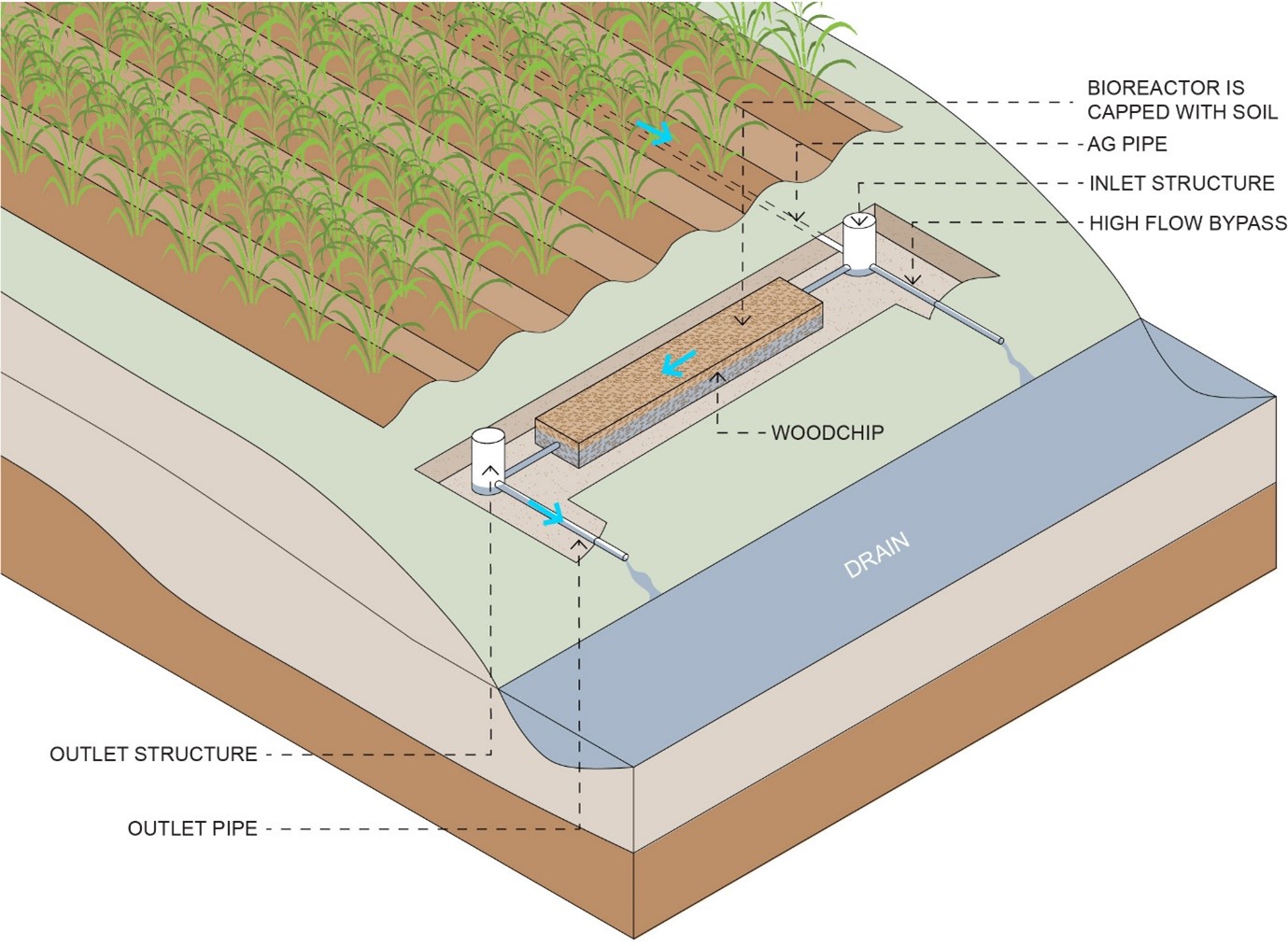
Ag-line bioreactor beds:
Inlet structure to connect to the ag-pipe or tile drain, with a high flow bypass and a spreader to disperse water evenly across the width of the bioreactor.
Outlet structure to regulate flow in the bioreactor bed. Drop boards can be used to regulate the water height and flow.
The woodchip should be enclosed in plastic to minimise soil entering the woodchip and enable the woodchip to be exposed later in the project if desired[3]
Topsoil of at least 0.1m depth placed on top of woodchip to prevent degradation of liner and to enable grass to grow on surface.
If the bioreactor is immediately upstream of a sensitive waterway, a structure to reoxygenate the discharge (e.g. rock riffles) should be installed downstream of the outlet.
Bioreactor walls:
the bioreactor wall must be orientated to intercept the shallow groundwater flow. The groundwater flow direction is determined during the site investigation and the bioreactor wall installed perpendicular to the groundwater flow.
If a shallow, low permeability layer (e.g. clay) is present, the base of the woodchip needs to be set slightly within (but not cut through) the low permeability layer so that groundwater does not flow around the woodchip.
Bioreactor walls are often excavated in a rectangular cross-section (standard excavator bucket) but can have a V-shaped or U-shaped cross-section if site conditions limit the use of vertical walls (e.g. sandy or saturated soils) (Figure 8).The top of the woodchip should be covered with a liner such as geofabric or plastic (to minimise soil entering woodchip and enable the woodchip to be exposed later in the project if desired[3]) and a layer of at least 0.2m of topsoil.
Disclaimer
In addition to the standard disclaimer located at the bottom of the page, please note the content presented is based on published knowledge of treatment systems. Many of the treatment systems described have not been trialled in different regions or land uses in Queensland. The information will be updated as new trials are conducted and monitored. If you have any additional information on treatment systems or suggestions for additional technologies please contact us using the feedback link at the bottom of this page.
References
^ L. Christianson, A. Castelló, R. Christianson, M. Helmers & A. Bhandari (2010), 'Technical Note: Hydraulic Property Determination of Denitrifying Bioreactor Fill Media', Applied Engineering in Agriculture. [online], vol. 26, no. 5, pp. 849-854. Available at: http://elibrary.asabe.org/abstract.asp??JID=3&AID=34946&CID=aeaj2010&v=26&i=5&T=1 [Accessed 26 May 2022].
^ Laura Christianson, James Hanly, Neha Jha, Surinder Saggar & Mike Hedley (2013), 'Denitrification bioreactor nitrous oxide emissions under fluctuating flow conditions', 2013 Kansas City, Missouri, July 21 - July 24, 2013. [online], American Society of Agricultural and Biological Engineers. Available at: http://elibrary.asabe.org/abstract.asp?JID=5&AID=43448&CID=miss2013&T=1 [Accessed 26 May 2022].
^abcdefg Manca, F, De Rosa, D, Reading, LP, Rowlings, DW, Scheer, C, Layden, I, Irvine-Brown, S, Schipper, LA & Grace, PR (September 2020), 'Nitrate removal and greenhouse gas production of woodchip denitrification walls under a humid subtropical climate', Ecological Engineering. [online], vol. 156, p. 105988. Available at: https://linkinghub.elsevier.com/retrieve/pii/S0925857420302767 [Accessed 26 May 2022].
^ Schipper, L, Robertson, WD, Gold, AJ, Jaynes, DB & Cameron, SC (2010), 'Denitrifying bioreactors—An approach for reducing nitrate loads to receiving waters', Ecological Engineering, vol. 36, pp. 1532-1543.
Last updated: 24 May 2022
This page should be cited as:
Department of Environment, Science and Innovation, Queensland (2022) Bioreactors — Planning and design, WetlandInfo website, accessed 8 May 2025. Available at: https://wetlandinfo.des.qld.gov.au/wetlands/management/treatment-systems/for-agriculture/treatment-sys-nav-page/bioreactors/planning-design.html


 — Department of the Environment, Tourism, Science and Innovation